
Key Takeaways
- Classify before you touch anything. PP duct maintenance is troubleshooting by class: sort the symptom into leaks, noise, or low airflow, because each class has a different first check.
- The fan is rarely the culprit. Low airflow is usually a system problem — blockage, leakage, or a stuck damper; a fan running backward delivers only a fraction of its rated flow.
- A blocked duct announces itself. Hood static pressure rises while flow drops, and deposits collect first at short-radius elbows and branch entries.
- PP joints are repaired by welding, not sealant. A leaking weld is fixed by removing the defective bead and re-welding; a weeping flange is fixed by alignment and staged re-torque, because PP joints relax over time.
- Maintenance runs on a baseline, not a hunch. Record an acceptance baseline, re-measure flow and static pressure on a schedule, and inspect PP-specific aging — creep, thermal stress, UV — before a fault becomes a shutdown.
An exhaust system that ran clean at commissioning rarely fails all at once. Suction fades at one hood, a whistle tracks the process speed, a flange weeps, a run of pipe plugs in the same spot again and again — and each symptom tends to get blamed on the nearest component. PP duct maintenance is diagnostic work: when a polypropylene exhaust run starts leaking, whistling, or losing suction at the hood, the fastest repair path runs through classification — leaks, noise, or low airflow — before anyone replaces a part. Copying sheet-metal habits onto plastic welds, or hanging a silencer on a restriction, costs more downtime than the original fault — so the symptoms below are sorted by class, each mapped to a first check, a first fix, and the measurement discipline that keeps the fault from returning.
Three Failure Classes, One Judgment Table: Leaks, Noise & Airflow
Diagnose by class before you dismantle anything: leaks, noise, and low airflow each have their own first check, and sorting the symptom into the right class tells you which sequence to run. That sorting is the working core of duct maintenance — the table below pairs the most-reported symptoms with their class, first check, and first fix.
| Symptom | Likely class | First check | First fix |
|---|---|---|---|
| Suction weakens at the hood | Airflow | Measure the hood-to-source distance — capture fades fast past 1.5 duct diameters — and compare flow and static pressure with the acceptance baseline | Run the low-airflow checklist in the next section |
| Fumes escape past the hood face | Airflow | Time smoke at the hood face and confirm it still holds at least 50 fpm — the rule-of-thumb minimum, subordinate to the contaminant standard | Locate the flow loss before touching the hood |
| The same section plugs over and over | Airflow (blockage) | Treat constant plugging as inadequate transport velocity or condensation wetting the particles | Fit a cleanout door there and confirm the transport velocity suits the contaminant being conveyed |
| A whistle that rises and falls with process speed | Noise | Compare the duct velocity with the acoustic velocity criteria for the duct’s position and shape | Hunt the restriction — a throttled damper, a sharp reduction, or a partial blockage |
| Clicking at fan start and stop, or backflow after shutdown | Noise | Operate the backdraft damper by hand and watch for a bound or stuck blade | Service or replace the damper |
| Hissing at a joint, drips below it, or daylight through a flange | Leak | Soap-solution test the joints one seam at a time | Re-weld the bead or re-torque the flange — never sealant |
| A visible sag along a horizontal run | PP aging | Check hanger spacing, band width, and point loads crushing the shell | Correct the support — wider bands, proper spacing, no point loads |
| Low airflow while the fan still turns | Airflow | Verify fan rotation first — a centrifugal running backward delivers only 30–50% of rated flow | Work the low-airflow checklist in order |
Use the table as a decision order, not a menu. Start at the measurement layer: confirm where the hood static-pressure taps sit, what the acceptance baseline reads, and whether the readings have drifted. Any tap that moves more than 5% between readings is a significant finding; shifts under 5% are routine. Every first check is non-invasive, so cheap evidence comes before anyone pulls the fan or opens a weld.
Two rows deserve a second reading. The reversed-fan row looks like a dying motor and is usually a rotation check; the sag row is not a leak or an airflow fault but the leading edge of PP aging. Keep the classes separate when symptoms overlap — a sagging run can open a welded joint, but repairing the bead does not correct the sag. Classify the symptom against this table first, and decide which of the three failure classes you are fighting before scheduling any work.
Duct Airflow Problems: Locate the Loss Before You Touch the Fan
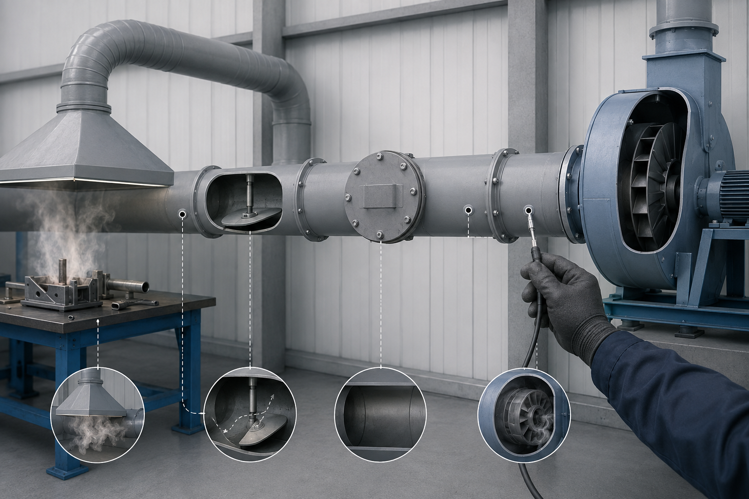
Most duct airflow problems live in the system, not the fan. The sequence below runs from the system inward until the readings name the culprit.
System-level first: what the fan is fighting
When airflow fades, one of three things has moved: duct resistance has risen — a retrofit, a filtration upgrade, or buildup on the duct walls — fan capability has dropped through rotation, speed, belt slip, or a fouled wheel, or the operating point where the fan curve meets the system curve has drifted.
Read the controls before the hardware. A variable-frequency drive and a manual damper throttling the same airstream fight each other, and the system reads like a failing fan; bearings and motors that fail repeatedly are usually symptoms of off-design operation, not defective parts. Resistance changes are curve changes — the sizing and design guide covers that side.
The low-airflow checklist, in order
Row eight of the judgment table — low airflow with the fan still turning — lands here as check 1: rotation. The sequence follows OSHA’s ventilation investigation manual, compressed to floor-level checks.
| Check | What you need | Normal vs abnormal |
|---|---|---|
| 1. Fan rotation | Rotation arrow on the housing | Normal: blades sweep with the airflow. Abnormal: reversed — a backward-running centrifugal delivers only 30–50% of rated flow |
| 2. Fan RPM and belt | A tachometer; belt condition | Normal: shaft speed on nameplate. Abnormal: a slipping belt, or a new belt still stretching |
| 3. Fan wheel and casing | A look through the inspection door | Normal: wheel and casing clean. Abnormal: material caked on blades and casing |
| 4. Hood static pressure and flow | Hood gauge against flow | Normal: they move together. Abnormal: high hood static pressure with low flow — restricted ductwork; open the cleanout doors |
| 5. Dampers and blast gates | A walk past every gate | Normal: gates set as designed. Abnormal: a gate closed or throttled — including one throttled to quiet a noise complaint |
| 6. Air cleaner | Cleaner gauges or the media | Normal: media clean, gauges steady. Abnormal: loaded cartridges or bags choking flow |
| 7. Weather cap gap | Cap-to-outlet clearance | Normal: about 3/4 duct diameter. Abnormal: anything tighter — and a weather cap itself is not recommended; it throttles the discharge |
| 8. Make-up air | Supply openings and room pressure | Normal: replacement air enters freely. Abnormal: a starved room; negative pressure drags fan output down |
| 9. Design review | Original design drawings | Normal: none of the three. Abnormal: short-radius elbows, sharp branch entries, or undersized ducts — a shortfall designed in, not lost in service |
Signature reading: hood static pressure patterns
The taps turn the checklist into a verdict — eight signature patterns cover the common faults. A partial blockage raises the reading upstream while flow falls, a hole pulls the reading down, a loaded air cleaner and a plugged stack outlet lift their own segments, and a single tap moving while its neighbors hold points to the tap or the reading itself.
When fan speed holds steady and fan total pressure (FTP) climbs, airflow through the fan has dropped; FTP falling at unchanged speed means flow has increased. Because flow varies with the square root of hood static pressure, a 30% drop corresponds to roughly a 15% loss of flow, a 50% drop to about 29%. Any tap that moves more than 5% is a finding.
Pattern-reading is what makes duct maintenance diagnostic: work the checklist in order, and you can decide from the readings whether the system or the fan is lying. A high-pressure, low-flow signature means restricted ductwork, and the next section maps where those restrictions form first.
Duct Blockage: Why Industrial Ducts Clog and Where They Clog First
Deposits settle where velocity and direction change together, which is why one section plugs every few weeks while the rest of the network runs for years.
Why industrial ducts plug
In duct maintenance, constant plugging at the same section is the classic verdict: inadequate transport velocity, or condensation wetting the particles until they stick. Transport velocity rarely fails all at once: a hood added, a blast gate relocated, high-friction flexible duct dropped into the run, a retrofit nobody rebalanced — each resets the balance point, and material settles at the new, slower speed.
Wet material plugs by a different route: once condensation wets the particles, dust that flew cleanly at commissioning turns sticky and builds a layer the airstream can no longer strip. Both routes end at the same question — is the airspeed still what the material requires? Transport velocity is set per contaminant — OSHA’s Table G-4, for example, lists 4,500 fpm branch / 3,500 fpm main for grinding dust — so any velocity standard must be matched to your contaminant, not copied.
Where they plug first
Deposits concentrate where the airstream turns, steps, slows, or pauses. Six positions account for most plugging, and the same fittings wear: grit scoured around a bend thins the wall long before the deposit closes it, which is why wall thickness selection belongs in the same review.
| Clog-prone position | Why deposits settle there | Prevention & monitoring |
|---|---|---|
| Short-radius elbows | Particles cannot follow the turn and settle in the pocket just past the bend | Cleanout door at the worst bends; tap the wall around them |
| T-branch connections | The blunt junction forms a dead zone, and material falling down the branch stays there | Cleanout access at the branch; re-walk it after any flow change |
| Diameter changes and velocity steps | A sudden enlargement drops the airspeed, and the eddy behind the step collects material | Door just downstream; recheck transport velocity after every change |
| Capture hoods and enclosures | Coarse material settles in the throat or plenum whenever the airspeed dips | Hood throat on the walk-through route; monitor the hood static tap |
| Air cleaner and scrubber sections | Loaded media and wet sections collect material that throttles the system | Watch the cleaner gauges; keep an inspection door on wet sections |
| Long horizontal runs at low velocity | A run near the bottom of its velocity margin settles along the invert and grows toward a plug | Tap for build-up on a schedule; recheck after any change |
A cleanout door and a monitoring note turn each fitting from a surprise into a scheduled stop.
Confirming a blockage without opening it
The readings confirm it before any door opens: hood static pressure climbing while flow falls is the signature of a forming duct blockage, and any tap beyond 5% is a finding. A blockage also answers a knock: tapping the suspect run finds where the sharp ring turns dull.
Smoke supplies the number behind the knock: release a puff, time it over a known distance — 2 ft in 2 s is about 60 fpm — and compare that speed with what the contaminant requires. A slow reading at a suspect fitting, plus a dead sound under the hammer, pins the section. Clearing deposits out of an industrial duct is maintenance work — not the residential duct-cleaning service homeowners book. Map your own runs against the six positions above and decide where the cleanout doors go.
Fix Duct Leaks the PP Way: Weld Repair and Flange Re-Torque, Not Sealant
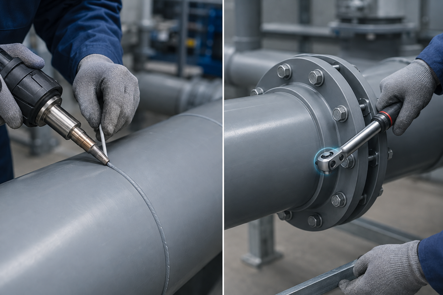
A blockage throttles the system from inside; a leak bleeds it at the joints, where hood static pressure drops instead of climbing. On welded PP the airtight element is the weld bead itself: a defective bead is removed and re-welded, and a weeping flange is re-aligned and re-torqued in stages — never sealed over. So a crew out to fix duct leaks starts at the bead and the bolt circle, not at a sealant gun.
Localize first: bubble check, pressure decay, and the metal framework as contrast
A soap-solution film at each joint marks the leak as a chain of bubbles — one seam at a time. For a longer run, isolate the section and watch the static reading decay.
Leaked air is transport air that never reaches the hood — capture fades nearby. Sheet metal manages leakage through the SMACNA duct leakage test manual and its seal classes; welded PP answers with the bead, so that framework is contrast, not a number source.
| Leak position | How to localize | PP repair path | Acceptance check |
|---|---|---|---|
| Porosity or cracks in a weld | Soap film at the seam | Remove the defective bead and re-weld at 305–315 °C | Glossy uniform bead; bubble check before concealment |
| Cold or overheated bead | Visual: dull under-fused bead, or charred surface | Cut the bead out; re-weld on the same chain | Glossy uniform bead; no unmelted rod, no char |
| Flange gasket weep | Soap film around the bolt circle | Check parallelism, then staged re-torque to the manufacturer’s target | Even gaps at the eight-point check; dry at re-check |
| Damaged flange face | Scoring or warp on the face; uneven gaps | Replace the flange ring or fitting | Faces parallel at the eight-point check; no bubbles |
| Mechanical (coupling) joint | Soap check at the gasket line | Reseat to full depth; renew the seal or the coupling | No bubbles at operating flow |
| Cracked pipe section | Visible crack or weep; pressure decay confirms | Cut the section out; splice in a replacement with a PP air duct coupling | Each new joint bubble-checked before return to service |
Welded joints: remove the defective bead and re-weld
Porosity, cracks, a cold under-fused bead, an overheated charred one — all four get the same repair: remove the defective bead and re-weld on the installation chain, 305–315 °C measured 5 mm outside the nozzle center, confirmed by a test weld before the repair bead is laid. The PP duct installation guide documents that DVS-based chain.
Acceptance is visual first, then wet: a sound bead reads glossy and uniform, a dull or chalky bead fails before the soap film comes out.
Flanged joints: alignment, staged re-torque, and the 24–48 h follow-up
A flange that weeps long after commissioning is rarely a failed gasket — it is PP under bolt load. Polypropylene creeps, so bolt stress relaxes; re-torque 24–48 h after initial tightening, and keep flanges on the periodic re-torque list.
When a flanged joint leaks, alignment comes before torque: check the gap at eight equally spaced points — uneven gaps mean the faces are not parallel. With the faces parallel, re-torque in staged rounds of roughly 30%, then 50–70%, then 100% of target torque, the target from the manufacturer’s table — and never tighten or loosen a joint under pressure.
What sealant is for—and what it is not
Cloth tape dries out on a warm duct run and loses adhesion. Mastic-and-tape recipes from residential sheet-metal work are neither method nor measure on welded PP.
Where sealant does belong is narrow — gasketed mechanical interfaces and threaded connections — and which product belongs to the duct insulation and sealing guide. On welded joints and bolted flanges, most duct repair is joint restoration: weld, flange, or coupling.
Three paths carry every leak in the table, and the localization readings decide which applies: re-weld the bead, re-torque the flange, or replace the section — and reject sealant-and-tape fixes.
Duct Noise: Sort Velocity Whistle, Damper Rattle and Fan Vibration
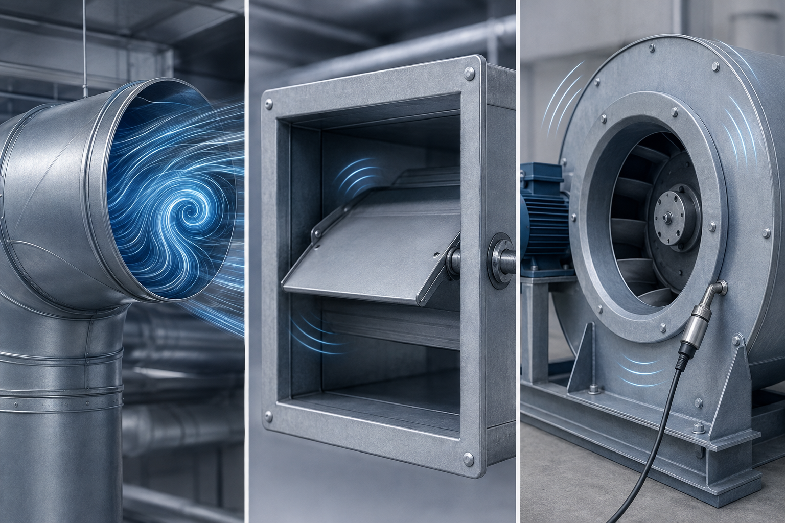
Leaks localize at a joint; noise does not, so sort duct sounds into one of three families — flow-generated, damper, or fan vibration — each with its own first check.
Sort the three noise sources first
A whistle that rises and falls with process speed is flow-generated noise — hunt the restriction instead of hanging attenuation on it. Flow-generated noise rises with air velocity, and every elbow, fitting, and damper adds sound of its own, so the whistle lives upstream of where it sounds loudest. Clicks at start and stop, or backflow after shutdown, name the backdraft damper; a low-frequency rumble with vibration is mechanical — fan, foundation, or flexible connection — and that rumble is a symptom to trace.
The noise–airflow interlock is where sorting pays. One documented case shows the trap: a worker partially closed a damper “to reduce the noise,” and flow dropped with it — the throttled gate the airflow checklist flags. Closing a damper files a second fault under the first.
| Sound | Likely source | Check | Industrial fix |
|---|---|---|---|
| Whistle that tracks process speed | Flow-generated noise at a restriction | Compare duct velocity with the acoustic velocity criteria for position and shape, against the ≈2,600 fpm occupied-space reference | Find and clear the restriction — rebalance or resize, not a silencer |
| Whistle fixed at one fitting | One elbow, branch entry, or damper edge | Walk the run by ear; read velocity at the fitting | Ease the velocity or refit it long-radius |
| Click or clatter at start and stop | Backdraft damper blade binding | Operate the damper by hand; watch blade travel | Free the blade, reseat it, or replace the damper |
| Backflow after shutdown | Blade stuck open or unseated | Watch the blade settle; check seat and counterweight | Reseat or replace the damper |
| Low-frequency rumble with vibration | Fan, foundation, or flexible connection | Trace by hand: bearings, base bolts, flex connection | Tighten or isolate the mechanical chain; fan teardown is specialist work |
| Background hum growing over weeks | Buildup or a loaded cleaner shifting the operating point | Compare hood static pressure and flow with the baseline | Run the low-airflow checklist; recheck against baseline |
Velocity check against acoustic criteria
When the sound is flow-generated, velocity turns the complaint into a measurement. ASHRAE’s acoustic criteria set maximum duct velocities by position and shape — for reference, a round main duct in an occupied space sits near 2,600 fpm at the RC-35 band, with branches scaled to about 80% and terminal connections to 50% or less. Read them as a design velocity-limit reference, not a maintenance target — the design-side noise principles live in the air duct design principles guide.
Excess velocity exacts a double toll: the whistle grows, and fast, grit-laden air scours the duct walls, so a high reading points at a restriction or an undersized section. What counts as abnormally loud has a plant context: factory spaces typically run 40–65 NC, roughly 50–75 dB(A), and a whistle standing clear of that background is a finding.
Backdraft dampers and start/stop noise
Start-and-stop clatter and shutdown backflow live at the backdraft damper; operate it by hand and watch whether the blade travels cleanly or binds. The fix runs from freeing and reseating the blade to full replacement — the PP backdraft damper page shows the interfaces. Choosing the damper itself is a vent-selection matter the separate duct vent selection guide covers; here, the task is whether the damper is the source.
Balance fixes answer velocity; component fixes answer a bound blade or a rough-running fan. Measure the velocity and sort the sound first — then decide between a balance fix and a component fix, instead of buying a silencer for a restriction problem.
Measure Before You Conclude: SP Taps, Traverse and Baseline Comparison
Every verdict so far has leaned on a reading. The measurement layer is short: what to measure, where it sits, and how to read the result.
What to measure and where
Static pressure is the working signal, and the signal is only as good as its tap. Tap hood static pressure 4–6 duct diameters downstream in a straight run, and treat any tap that moves more than 5 percent as a finding, not noise. Fittings distort readings taken closer in, so every tap sits in a straight stretch. Duct velocity follows the same placement rule: a single-point reading screens; the traverse certifies.
Where the number has to stand up — acceptance runs, baseline records, post-repair verification — the traverse replaces the single point: six or ten stations, two or three passes, rotated 90° or 60°. Methods and instrument limits follow OSHA’s ventilation investigation manual; the table gathers them.
| Measurement | Where & tool | How to read |
|---|---|---|
| Hood static pressure | Straight-run tap 4–6 duct diameters downstream of the hood | Compare with the acceptance baseline; beyond 5% is a finding, under 5% is routine drift |
| Duct velocity, single point | Pitot in the straight run, 4–6 D downstream and 2–3 D upstream | Averages about 90% of centerline velocity; velocity pressure about 81% |
| Duct velocity, traverse | 6 or 10 stations across the duct, 2–3 passes, rotated 90°/60° | The accurate flow figure for the baseline record |
| Transport velocity, smoke | Timed smoke puff over a known distance (V = D/T) | 2 ft in 2 s is about 60 fpm — the screen from the blockage section |
| Face velocity, anemometer | Vane at hoods and openings | Reads only above 50 fpm; unusable in dust or mist; calibrate at least annually |
| Static pressure, manometer | Gauge-line taps | Rarely usable below 800 fpm (velocity pressure under 0.05 in. wg) |
Reading the numbers
Reading follows two rules. Convert first: flow varies with the square root of hood static pressure, so a 30% drop in a tap reading is roughly a 15% flow loss, a 50% drop about 29% — at constant fan speed. Then threshold: movement beyond 5% at any tap is significant; under 5% is common and ignorable.
Name the pattern before acting on a number: the airflow section’s eight-pattern checklist pairs tap movements with faults; a lone moving tap points at the gauge and the record, not the ductwork.
Baseline comparison as the maintenance loop
At acceptance, log the traverse figure and every static-pressure tap from hood to discharge; that record is the baseline. The loop compares against it: CCOHS’s industrial ventilation guidance directs teams to measure airflow and static pressures in the duct network on a regular, scheduled basis, by trained people with specialized instruments. Monitoring is not housekeeping: “almost all IV standards and codes require monitoring of the ventilation system,” as AIHA-published troubleshooting guidance puts it.
The loop closes itself: baseline at acceptance, re-measurement against it, any tap beyond 5% triggering the airflow checklist, localization, repair, and a confirming re-read that updates the record. Same taps, same instruments, same conditions keep the comparison honest. With the tap positions and thresholds above, decide which taps to install first and what a significant reading looks like on your own system.
PP Duct Maintenance Checklist: What to Inspect on a Schedule
The calendar question lands here: duct maintenance on a schedule turns reaction into routine. The checklist below is two lists in one — walk-through items any industrial duct shares, and aging checks only polypropylene needs. Plastic does not mean maintenance-free: PP fails at supports, joints, and on surfaces left to sun or chemistry.
Walk-through duct inspection items
The walk-through is the cheapest check: a plume escaping past a running hood is capture fading, a steady-period plug is transport velocity drifting, and dents and holes collect along impact lines.
Dust collecting on equipment around a joint betrays a leak upstream; an add-on tapped in without a rebalance rewrites the balance silently; a blanked cut-off leaves a path nobody documented.
| Check | What to look at | Abnormal signal | Action |
|---|---|---|---|
| Capture performance | Plume at each hood face, line running | Fumes curling back past the lip | Low-airflow checklist, airflow section |
| Weld bead appearance | Gloss and continuity on sample seams | Dull, porous, or cracked bead | Weld repair path, leak section |
| Flange condition | Bolt-circle gaps; weep stains | Uneven eight-point gaps; weep line | Staged re-torque, re-check at 24–48 h — leak section |
| Hangers and support bands | Band width, hanger spacing, point loads | Narrow strap; a point load crushing the shell | Respace and widen the supports (PP aging below) |
| Expansion compensation | Loop/offset movement; sliding supports | Compensator locked; anchor drifted; slide seized | Free the movement before a joint cracks (PP aging below) |
| Dampers and blast gates | Gate positions; backdraft blade travel | Gate tied open, or throttled to quiet a whistle | Damper checks, noise section |
| Interior surface and buildup | Knock test; cleanout-door sight at elbows and branches | Dull ring; layer on the invert | Clog-prone positions, blockage section |
| Outdoor UV surface | Chalk test on sun-exposed runs | Powder on the glove; gloss gone | Log the trend; shielding or stabilized grade (PP aging below) |
| Flow and static reconciliation | Hood taps and traverse against the baseline | Any tap beyond 5% of baseline | Baseline comparison, measurement section |
PP-specific aging checks
Two aging mechanisms belong on no sheet-metal checklist. Creep sag first: long-term deflection is the design limiter, rated against criteria such as 1 cm of sag after 10 years. Sight along horizontal runs for droop. Then thermal stress: polypropylene expands 72–90 ×10⁻⁶ m/(m·°C), six to eight times steel’s 10.8–12.5, so a long restrained run loads its joints cyclically on every heat-up; the expansion-compensation row carries the check.
On sun-exposed runs, record the UV trend — chalking that rubs off, corners turning brittle — and never a service-life date: stabilization, pigment, or shielding is the mitigation. Inside, check through the cleanout doors for swelling or fine cracking where the medium, concentration, or temperature has drifted.
How often: schedule from the baseline, not from a folklore number
No universal statutory interval exists for industrial ventilation ductwork. The authorities set duties, not calendars: OSHA’s ventilation standard requires exhaust systems be maintained in line with a recognized framework such as ANSI Z9.2.
The baseline sets the rhythm: a clean history earns a wider cycle, a fault history a tighter one, and any duct or airflow change earns a re-measurement. The plating and dip-tank standard, 29 CFR 1910.124, writes a quarterly inspection into that process — a special case, not a template — and laboratory hood programs re-check face velocity periodically against a typical 100 fpm, about 0.5 m/s. Before the first scheduled check, decide what your baseline record must contain — taps, flows and photos — because the schedule only means something against it.
Repair In-House or Stop the Line: the Self-Fix Boundary
The scheduled walk-through returns findings, and every finding needs a disposition: fixed in-house, or the line stops and a specialist is called. Most PP duct faults have a legitimate in-house fix; the discipline is knowing the stop conditions and writing them down before work starts. The table below draws that line.
| Situation | In-house action | Specialist | Stop condition | Verify after |
|---|---|---|---|---|
| Flange weep | Alignment, staged re-torque to target | Ring replacement if faces tilt | Weep returns after re-torque | Dry bolt circle at the 24–48 h re-check |
| Section plugs at a mapped fitting | Open cleanout door; clear, log the spot | Cut-in access beyond the doors | Plugs on a steady period — transport velocity, not housekeeping | Hood static tap back within 5% |
| Backdraft damper binds or backflows | Free and reseat the blade; replace if bound | Replacement damper, interface matched | Fault survives a reseat | Blade settles closed at next shutdown |
| Weld defect — porosity, crack, cold or charred bead | None — never patch a bead | Re-weld on the DVS chain, or coupling-spliced section | The defect itself: welding is specialist work | Glossy uniform bead; bubble check before restart |
| Flow low, fan still turning | System diagnosis first: rotation (backward gives 30% to 50% of rated flow), belts, wheel, gates | Fan teardown and dynamic balancing | Diagnosis points inside the fan | Taps re-read against baseline |
| Same component fails again | Stop swapping parts; review the system | Supplier review of the operating point | Second failure of the same part | Re-read confirms the operating point |
| Medium or process change | Hold the restart; document the change | Compatibility check, then a professional rebalance | The change, until cleared | New baseline recorded at restart |
The in-house side of the line
Three rows stay with the crew — care the system already expects. A weeping flange is creep relaxation at work: alignment first, then staged re-torque, with the verdict at the 24–48 h re-check. A blockage at a mapped fitting is a door away. A damper is bench work: free the blade, reseat it, replace it only when travel stays bound. When replacement wins, the airflow accessories selection guide walks the choice between manual, electric and backdraft valves.
The stop conditions
The four stop conditions sit where tolerances end — in the weld, the fan, the design assumptions. A weld defect is the clearest: the bead is a controlled process; its repair is a specialist re-weld on the DVS parameter chain or a section spliced in with a coupling — never a patch. A fan gets its system diagnosis first; teardown and dynamic balancing are specialist work. A repeated failure points at the system, not the part; a medium or process change rewrites the design assumptions. When a stop ends in a part, the shutdown doubles as the order — section ends, coupling splices, damper interfaces confirmed on the product pages.
Verify against the record
A repair is not finished until the readings confirm it: re-read the taps, and any tap still beyond 5% of the baseline sends the crew back to the checklist. Write the stop conditions down before work starts, and your crew can decide in the moment what stays in-house and what stops the line.
FAQ: PP Duct Maintenance and Troubleshooting
How often should PP ductwork be inspected?
No statutory interval exists; the authorities set duties, not calendars. The inspection section’s frequency heading carries the answer: monitor on a regular, scheduled basis, let the acceptance baseline set the rhythm, and re-measure after any duct or airflow change.
Can I seal a leaking PP joint with sealant or tape?
No. On welded PP the airtight element is the bead, so nothing brushed onto the outside restores the joint. The leak section’s table maps each position to its PP repair path: re-weld the bead, re-torque the flange, splice a crack with a coupling.
Why is airflow low but the fan runs normally?
A fan can spin perfectly and still underperform. Rotation leads the airflow section’s checklist, because a backward centrifugal delivers only 30% to 50% of rated flow; belts, the wheel, throttled gates, and a loaded cleaner come next. High hood static pressure with low flow points to restricted ductwork, not a dying fan.
How do I confirm a duct is clogged without opening it?
Read the signature before opening anything: hood static pressure climbing while flow falls, and a tap that has moved more than 5% between readings. A knock finds the dull ring, and the blockage section’s confirmation steps end at a cleanout-door look.
What causes whistling in an industrial duct?
A whistle that tracks air speed is flow-generated noise at a restriction: a throttled damper, a partial blockage. The noise section’s table sorts the families, and the acoustic velocity limits set the scale, near 2,600 fpm for an occupied-space round main. Closing a damper to quiet the run trades the whistle for lost airflow.
Does PP duct need less maintenance than metal?
Not less; different. Polypropylene does not corrode, so the leak paths metal systems fight never appear, but the material brings its own aging list: creep sag, thermal stress, UV chalking, and flanges that relax. The inspection section’s PP-specific checks carry that list.
| Question | One-line answer |
|---|---|
| How often should PP ductwork be inspected? | No statutory interval; the baseline sets the rhythm |
| Can I seal a leaking PP joint with sealant or tape? | Re-weld the bead; re-torque the flange; never sealant |
| Why is airflow low but the fan runs normally? | Rotation first — backward fans give 30% to 50%; high static with low flow means restricted ductwork |
| How do I confirm a duct is clogged without opening it? | Rising hood static, falling flow, a tap beyond 5%, a dull knock |
| What causes whistling in an industrial duct? | Flow-generated noise at a restriction; velocity near the ≈2,600 fpm reference |
| Does PP duct need less maintenance than metal? | Different checks, not fewer: creep, thermal stress, UV, flange relaxation |
These six answers let you decide the routine questions on the floor without re-reading the full guide.
Conclusion: Run Maintenance as a Loop, Not a Reaction
Duct maintenance runs as a loop, not a reaction — every fault becomes a scheduled stop instead of an emergency. The judgment table sorts the symptom into leaks, noise, or low airflow; the static-pressure readings and the low-airflow checklist tell whether the system or the fan moved; the blockage map and the noise table localize the cause; the PP repair path — re-weld the bead, re-torque the flange, or replace the section — completes the fix; the self-fix boundary marks where specialist work begins; and the baseline record carries the cycle forward, so each measurement compares against the last recorded run instead of against a memory. Replacement sections order against the φ20–600 mm standard outer diameter series, and the interfaces for couplings, dampers, and flange hardware confirm on the product pages before the order goes out. Run the judgment table on your worst symptom this week and decide what your baseline record contains — the next maintenance window then becomes a sequence, not a shutdown.