
Key Takeaways
- Straight PP duct pipe begins as resin pellets that are melted and pushed through a circular die.
- Calibration, cooling, haul-off, and cutting control roundness, wall consistency, and usable length.
- Hot-gas welding and extrusion welding are different processes with different parameter windows.
- A factory should be able to explain its weld procedure and show how it checks a representative joint.
- Ask which method, to which procedure, and how the result was checked—not just “is the duct welded?”
Polypropylene duct is usually made in two linked operations: continuous extrusion forms straight pipe, then controlled thermal welding turns pipe and fittings into a leak-resistant duct system. The important distinction is that the straight run is not simply “molded,” and a good weld is not a generic glue joint. Material temperature, hot-air temperature, travel speed, filler rod, and surface preparation all influence the finished joint.
For the wider material and application context, start with what PP air duct is and the PP air duct system guide. This guide focuses on the manufacturing decisions that affect a fabricated duct assembly.
Step 1 – Extrusion: How Is PP Duct Made From Pellets to Pipe?
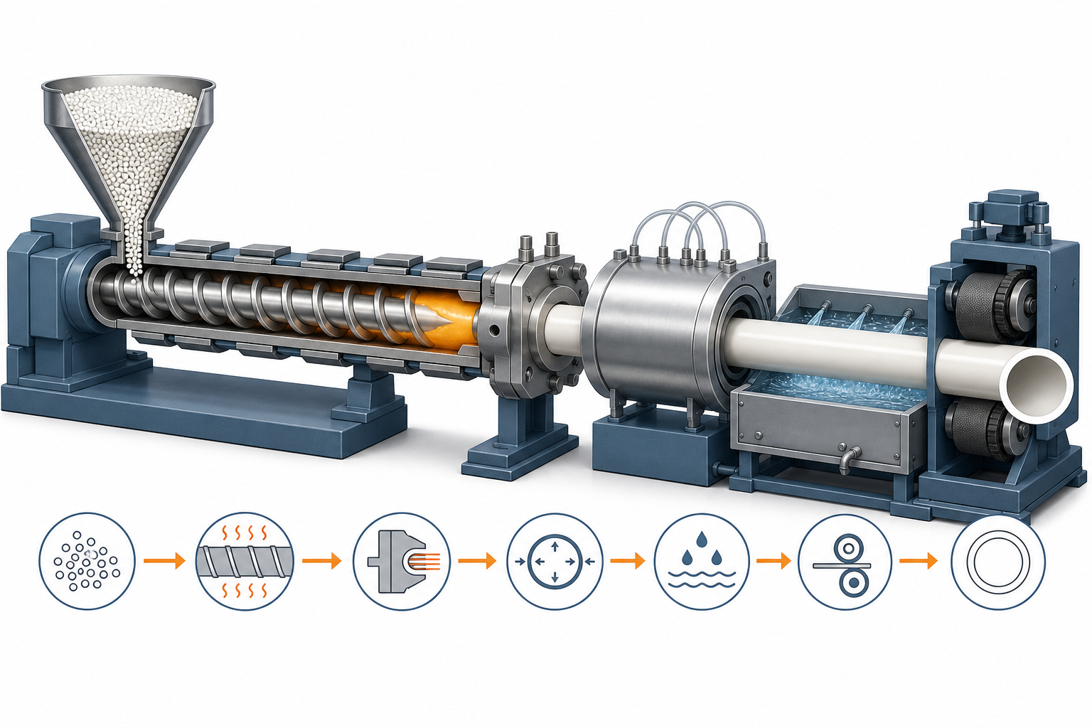
A straight PP duct section starts with polypropylene pellets and leaves the line as a continuously formed pipe. In a typical extrusion line, pellets enter a hopper, a rotating screw carries them through heated barrel zones, and the softened polymer is pushed through a circular die. The emerging profile is then sized, cooled, pulled at a controlled rate, and cut to the required length. That sequence matters because the pipe wall, diameter, and roundness are established before any fitter makes the first welded connection.
What Happens Inside the Extruder
The hopper is a storage and feed point; it does not create the pipe shape. The screw inside the barrel conveys, mixes, and heats the resin until it becomes a uniform melt. A general PP pipe/profile processing guide lists 200–250°C for cylinder zones and notes that the actual processing window must be confirmed against the resin and machine supplier’s guidance, rather than copied blindly from another line. For standard homopolymer grades the melt at the die is roughly 200–230 °C; filled or special grades need a higher setting, so confirm the melt range against the material datasheet. The die then creates the circular profile. In other words, diameter and wall are controlled by the die, melt condition, and downstream handling—not by the later welding operation.
That is why “extruded PP duct” should not be read as a universal quality claim. A stable line needs coordinated barrel temperature, screw output, die geometry, and puller speed. If the melt is uneven or the haul-off pulls too aggressively, the visible pipe can still look acceptable while wall consistency or roundness becomes harder to control. The manufacturing question worth asking is whether the supplier monitors those variables across the production run, not merely whether it owns an extruder.
A practical way to picture the process is a φ250 mm duct section (250 mm outside diameter) as a traceable example, not as a promised product specification. XICHENG’s published PP duct range is φ20–600 mm, so a 250 mm diameter sits inside the stated family range, but final wall thickness and tolerances still need to be specified for the project rather than inferred from diameter alone.
Sizing, Cooling and Cutting the Pipe
After the die, the soft profile must be supported before it can retain its shape. Pipe-extrusion references describe a vacuum calibration stage followed by cooling tanks: the vacuum stage helps prevent collapse while the pipe is still soft, and cooling water removes heat so the profile can solidify. A synchronized haul-off then keeps the pipe moving at a steady speed, while the cutter produces the requested straight length.
| Extrusion station | What it does | What the buyer can ask to verify |
|---|---|---|
| Hopper and screw | Feed, convey, and homogenize PP resin | Which PP grade is used and how material batches are controlled |
| Heated barrel and die | Bring the material to process condition and form the circular profile | Whether the manufacturer records process conditions for the run |
| Vacuum calibration and cooling | Hold the fresh profile while it becomes stable | How roundness and wall variation are checked after cooling |
| Haul-off and cutter | Maintain line speed and create usable length | How cut length and end condition are inspected before fabrication |
Cooling is not a cosmetic last step. PP contracts as it cools, so a controlled cooling and inspection routine is part of dimensional control. XICHENG’s SGS report GZMR260601945804 records a 0.5% material shrinkage value, but that report is material evidence—not a substitute for verifying the dimensions and fabrication tolerances of a specific order.
Why Uniform Wall Thickness Matters
Uniform wall thickness gives the next operation—a welded joint—a consistent edge to prepare and heat. A thin spot can change the amount of heat it absorbs; an out-of-round pipe can make fit-up uneven; a rough or damaged cut edge can leave a weak starting condition for a weld. These are connected manufacturing stages, not isolated departments.
For an industrial exhaust project, decide first whether the supplier can trace the pipe from resin grade through extrusion and post-cooling inspection. If the answer is vague, ask for a representative wall-thickness check and a sample of the intended weld procedure before you approve the fabrication route.
Process references: DRTS pipe-extrusion overview for the hopper-to-cutting sequence; PP extrusion processing guide for general processing ranges. The cited values are general guidance and must be confirmed for the PP grade, tooling, and project conditions.
From Straight Pipe to Duct System: Fittings and Connections
Extrusion makes efficient straight pipe, but a working exhaust route also needs elbows, branches, reducers, dampers, clean-outs, and terminations. These parts are where a duct system changes direction, changes diameter, connects to equipment, or allows access for maintenance. A specification that describes only pipe diameter and wall thickness is therefore incomplete: the fitting geometry and the joint method determine whether the system can be assembled, supported, and tested as intended.
Three Ways Fittings Are Made
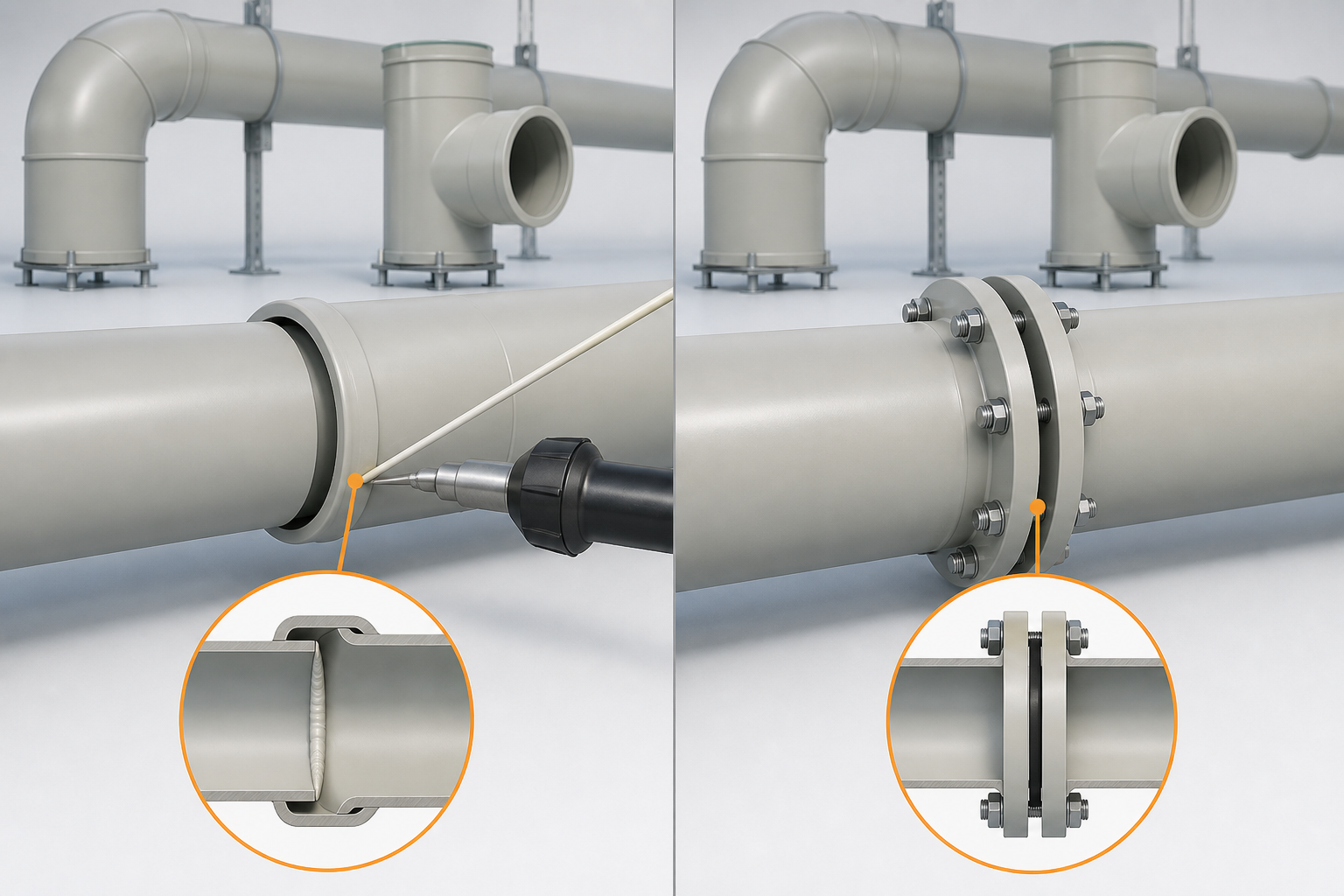
The first pathway is a molded fitting. In socket-based systems, the pipe end is inserted into a formed socket and back-welded with a compatible PP rod. Simtech’s AirTech PP duct system, for example, describes molded sockets and lists its own duct pipe availability up to 55 in and molded fittings up to 39 in. Those figures describe that manufacturer’s product family, not a universal size limit, but they illustrate why molded geometry is common where repeatable elbows, tees, and reducers are needed.
The second pathway is fabricated assembly. A shop can cut PP pieces to shape and join them with controlled thermal welding, which is useful for non-standard branches, transitions, rectangular connections, or project-specific dimensions. The third is thermal forming: a heated PP section can be formed into a controlled shape before cooling. A supplier may use more than one pathway in the same project, so a phrase such as “molded PP duct” should never be assumed to describe every component in an assembly.
| Fitting pathway | Best fit | What to confirm before approval |
|---|---|---|
| Molded socket or standard fitting | Repeating round elbows, tees, reducers, and dampers | Socket dimensions, compatible pipe series, and back-weld procedure |
| Fabricated and welded fitting | Transitions, non-standard branches, larger custom geometry | Weld method, material compatibility, inspection access, and support arrangement |
| Thermally formed section | Shapes where a formed radius or transition is specified | Forming method, minimum wall condition after forming, and dimensional check |
The useful distinction is not whether a fitting looks factory-made. It is whether the manufacturer can identify its fabrication route and show that the route matches the system’s pressure, temperature, chemical exposure, and support conditions. For corrosive-air systems, material selection and the connection design must be considered together; a ventilation duct sizing and design review can help establish those wider project inputs.
Socket Joints vs Flanged Joints
A socket joint is a permanent thermoplastic connection: the pipe and fitting are positioned, then the accessible seam is welded with compatible PP filler. It is compact and can be efficient for repeated round components. A flanged joint is a mechanical connection between two duct sections; it normally provides a demountable boundary where equipment, a damper, or a future maintenance section may need to be removed. The flange itself does not replace the need to specify sealing, bolt pattern, and load support.
Neither connection is automatically better. A socket connection can reduce loose hardware and suit a continuous route, while a flanged connection can make a connection point accessible. The correct choice depends on whether the joint must be opened later, how the section will be supported, and what leakage-control approach the project requires. Fittings should also be matched to the duct series—XICHENG’s documented PP duct range is φ20–600 mm—so socket and flange boundaries line up with the pipe family. A PP duct flange should therefore be selected as part of the connection detail, not as an isolated accessory.
One manufacturing detail stays constant across both paths: a welded PP joint should use compatible material and a documented process. Simtech explicitly calls for a welding rod of the same material for its PP system; that is a sensible compatibility check, but it does not eliminate the need for correct heat input and surface preparation, covered in the next sections.
When you review a duct submittal, ask the supplier to mark which fittings are molded, fabricated, or formed, then identify every socket and flange boundary. That one drawing-level check lets you decide where the project needs weld records, where it needs demountable access, and where it needs more detail before fabrication begins.
Fitting reference: Simtech AirTech polypropylene duct systems. Product-size examples are Simtech-specific and are not presented as XICHENG specifications.
Step 2 – Hot Gas Welding: The Standard Joining Method
Hot gas welding is the standard way PP duct components are joined: a heated-air gun softens the base material and a compatible PP filler rod, and the two fuse into one homogeneous joint as the rod is laid into the groove. This is the process normally used to close the seams and fixings of a fabricated duct run, and it is the method whose parameter tables European and American manufacturers reference, such as the hand-welding table based on DVS 2207-3. The weld is not a glue joint, and it is not injection molding; its quality depends on three controlled variables—temperature, applied force, and travel speed.
Welding Parameters That Control Joint Quality
The table below is the LEISTER hand-welding parameter set for polypropylene (types PP-H, PP-B and PP-R), published as based on DVS 2207-3. Temperature is measured 5 mm from the nozzle opening center; the air flow is cold air drawn in at ambient pressure; and speed depends on the filler rod diameter and groove geometry.
| Parameter | PP-H / PP-B / PP-R | Where it is measured |
|---|---|---|
| Hot gas temperature | 305–315 °C | 5 mm from the nozzle opening center |
| Hot gas volume flow | 40–50 l/min | Cold air drawn in at ambient pressure |
| Welding speed | 60–85 mm/min | Depends on rod diameter and groove geometry |
| Welding force, 3 mm rod | 8–10 N | Applied to the rod during laying |
| Welding force, 4 mm rod | 20–25 N | Applied to the rod during laying |
These values are a starting window, not a fixed recipe. Ambient temperature, material batch, and groove shape shift the practical setting, which is why the parameter tables themselves state that test welds must be carried out and adapted. A welder who cannot state the window—or who gives the same blanket settings for summer and winter work—has not demonstrated process control. Note also that the melt stage belongs to the weld, not to the pipe: by the time the joint is made, the extruded pipe has already cooled and been cut (Step 1).
Rods, Torches and Technique
Filler rods are typically 3–4 mm PP rod—the parameter tables give separate force values for 3 mm and 4 mm rods—and suppliers commonly require a rod of the same material as the duct so the joint fuses cleanly instead of introducing a second, incompatible zone. Confirm the exact PP type rather than assuming “polypropylene” is one material. The torch is a hot-air gun with an adjustable output—common units are adjustable over roughly 20–600 °C—so the operator sets the dial to the PP target band rather than guessing by sight. A temperature check near the nozzle is a fair validation step.
Technique matters as much as the dial. The joint surfaces should be clean, dry, and free of oil or dust; the gun preheats and sweeps the groove to distribute heat; and the rod is pressed into the softened material at a steady angle and speed. If temperature is too low or travel too fast, the rod does not fully fuse—a cold weld. If heat is excessive, the material decomposes instead of flowing. Both outcomes lower joint strength and are usually visible on the weld surface, as covered in the weld-quality section below.
When you compare suppliers, ask for their written hot-gas procedure: rod type and compatibility, target temperature window, speed, and how test welds are verified. A documented window plus a demonstrated test weld is far more informative than a statement that the factory “can weld PP.” That check also matters for the PP air duct advantages you are counting on, such as corrosion resistance and long service life—the material only helps if the joint is sound.
When to Use Extrusion Welding Instead
Extrusion welding is chosen where a hand-welded rod bead is too slow or too small: a hand extruder melts filler material and deposits it as a continuous bead that can fill a larger seam in one pass, while hot gas from the same tool preheats the joint. It is not a different material or a better weld by default—it is the right method for larger weld volumes, thicker sections, and longer production seams, and it has its own parameter window.
Extrusion Welding Parameters (DVS 2207-4)
The LEISTER extrusion-welding table, published as based on DVS 2207-4, gives the following window for PP (types PP-H, PP-B and PP-R). The material temperature is measured with an insert thermometer at the extrudate outlet of the hand extruder, and the hot gas temperature is measured 5 mm from the nozzle opening center.
| Parameter | PP-H / PP-B / PP-R | Where it is measured |
|---|---|---|
| Extruded material temperature | 210–240 °C | Insert thermometer at the extruder extrudate outlet |
| Hot gas temperature | 210–300 °C | 5 mm from the nozzle opening center |
| Hot gas volume flow | 300 l/min | Cold air drawn in at ambient pressure |
| Welding speed | ~300 mm/min | Depends on preheating and joint geometry |
As with hand welding, ambient temperature and material configuration shift the practical setting, and the DVS 2207-4 supplement frames the reference values—including a welding speed between 200 and 350 mm/min depending on the joint—with a similar test-weld requirement. The raw numbers alone do not produce a sound joint; the operator must preheat the groove, keep the bead consistent, and adjust to the actual conditions.
Hot Gas vs Extrusion: Choosing the Method
Use these two methods as complementary tools, not as rivals:
| Decision input | Hot gas welding (DVS 2207-3) | Extrusion welding (DVS 2207-4) |
|---|---|---|
| Joint size and material thickness | Fillet welds, repairs, thin sections, field work | Larger beads, thicker walls, long production seams |
| Filler form | PP rod, typically 3–4 mm | Melted filler deposited from the extruder |
| Throughput per pass | Lower deposition | Higher deposition per pass |
| Typical fit | Seam closing, small fittings, on-site work | Tank and duct shop fabrication, extended seams |
| Same discipline | Clean surfaces, correct temperature, test weld | Clean surfaces, preheat, consistent bead, test weld |
The decision is geometric and economic, not a quality ranking. A shop that welds a 6 mm wall with a 3 mm rod hand torch is choosing a slow, shallow process; a 4 mm rod deposits more material per pass, so the rod size should suit the groove. A shop that extrusion-welds a thin seam may over-fill or distort the joint. The right question is therefore not “which machine do you use?” but “which method do you apply to which joint, and where are the parameter records and test-weld results?” With that answer in hand, you can choose the method per joint and state exactly what evidence to request before fabrication begins.
What Weak Welds Look Like: Cold Welds, Overheating, Contamination
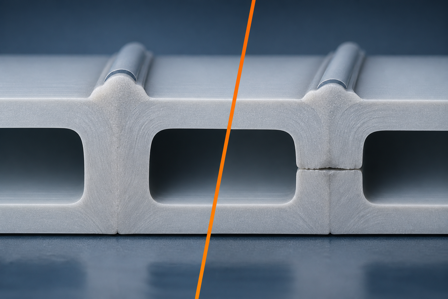
A weak PP weld is usually a parameter or preparation problem, and most of them are visible before the system ever runs. The three failure classes a buyer should recognize are incomplete fusion (cold welding), overheating, and contamination. None of them needs laboratory testing to suspect: they have readable visual signs, and recognizing them is the lowest-cost quality check in the whole manufacturing chain.
Three Failure Modes and Their Visual Signs
| Failure mode | Typical cause | Visual sign | What it means for the joint |
|---|---|---|---|
| Cold weld (incomplete fusion) | Torch temperature below the PP window (e.g., below the 305–315 °C hand-welding band, or travel speed above the 60–85 mm/min band), or rod laid before the base is soft enough | Dull “skinned” bead, a visible boundary line between rod and base, bead that can be lifted or that flakes at the edge | Load-bearing cross-section is incomplete; the joint can fail well below design load |
| Overheating / decomposition | Temperature above the top of the 305–315 °C band or the gun held too long in one place | Brownish or amber discoloration, light smoke during welding, bubbles or char | Decomposed material is brittle and its chemical resistance is degraded |
| Contamination / porosity | Oily, dusty, damp, or freshly cut surfaces; incompatible filler material | Voids or bubbles in the bead, pinholes, uneven gloss, poor wetting between rod and base | Local weak spots and leak paths; contaminant may react with the conveyed air |
Why Test Welds Are Non-Negotiable
The parameter windows in the two welding sections above are only the starting point, but the same nominal settings behave differently on a cold winter job, a different resin batch, or a thicker wall. That is why the reference tables state that test welds must be carried out and parameters aligned to actual conditions. A test weld is the point where process control becomes visible: the operator welds a representative joint with the same rods (typically 3 mm or 4 mm) and the same torch, breaks or inspects it, and confirms the bead fused rather than sat on the surface.
For a buyer, the practical equivalent is to ask for the test weld the factory actually made for your project and how it was judged. If the answer is a sample with a uniform, fully fused bead, the process is under control. If the answer is vague or the sample shows a cold-weld line, treat the entire fabrication batch as unproven until a corrected procedure is demonstrated. You do not need a laboratory to make that call—a clean, fully fused bead on a representative joint is the baseline evidence you were looking for.
How a Reliable Factory Checks Quality
A reliable PP duct factory checks the same things you would check, but continuously and in writing. Quality control in duct fabrication is not one test at the end; it is a set of checks along the manufacturing chain—material, extrusion, and welding—that produce records you can review before you approve an order.
Checks During Production
Material control starts before extrusion: the PP grade should be identified per batch, and incoming resin should be traceable to its supplier. During the extrusion run, a factory checks dimensional stability—wall thickness, roundness, and cut length—rather than relying on the machine setting alone. During welding, the checks are the ones from earlier: correct material temperature, correct travel and rod technique, and a test weld at the actual site conditions. Depending on the application and specification, completed joints may also be verified by visual inspection and, where required, by leak or pressure testing. The point is that every step has a defined check, not that every step uses the same test.
Documentation You Can Ask For
The records that separate a managed shop from an improvised one are ordinary business documents:
| Document | What it demonstrates |
|---|---|
| Material certificate for the PP grade | Traceable resin, not an unverified “polypropylene” |
| Process records (extrusion and weld parameters) | The window was set and followed for your order |
| Test-weld sample and judgment record | Fusion was confirmed before the batch ran |
| Dimensional inspection report | Wall, roundness, and length met the specification |
| Third-party material report (if offered) | Independent data on material behavior, e.g., the SGS report for XICHENG EP LTD that records 0.5% shrinkage and 16 MPa internal pressure, alongside its ISO 9001 and ISO 14001 certificates |
Ask for this package as a set, not as isolated documents. A supplier that can produce material, process, and weld evidence for your specific order is describing an audited process; one that can only promise quality in conversation is asking you to trust without verification. The same checks apply across the published duct series, from φ20–600 mm. When you are ready to narrow suppliers, compare how each one documents the checks above before discussing price or lead time on a polypropylene PP air duct.
Questions to Ask a PP Duct Manufacturer
The five questions below convert everything in this guide into a five-minute supplier call. Each question targets one part of the manufacturing chain and gives you a concrete way to judge the answer.
The Five Questions
| # | Question | What a strong answer looks like |
|---|---|---|
| 1 | For each fitting in this system, is it molded, fabricated/welded, or thermally formed? | A per-component answer, not “we have everything” |
| 2 | Which weld method do you use for each joint type, and what are your temperature and speed windows? | Specifics such as the ranges in this guide—305–315 °C hot gas with 60–85 mm/min for hand welding (measured 5 mm from the nozzle), 210–240 °C extrudate for extrusion welding—measured at the stated points |
| 3 | Where is the test weld for my project, and how was it judged? | A representative sample with a fully fused bead and a record of the check |
| 4 | What documents ship with the order? | Material certificate, parameter records, dimensional report, and any third-party material report |
| 5 | Which checks happen during extrusion and after welding? | Wall/roundness/length checks and visual inspection plus leak or pressure testing where specified |
These five questions are also your comparison tool across suppliers. A supplier that answers all five with documents, samples, and parameter records has a managed process; one that answers with assurances needs more evidence before it earns the order. For a full buying walk-through, including how to read quotations and specifications, see how to buy PP duct.
FAQ: How Is PP Duct Made? (Welding, Temperatures, Strength)
Is a welded PP duct as strong as the pipe itself?
The weld can approach the strength of the pipe, but only when the joint is correctly made. If the filler rod is compatible, the surfaces are clean, the temperature and speed stay in the material’s window, and the test weld confirms full fusion, the joint becomes a homogeneous section. If any of those conditions fails, the weld is the weakest point of the system. That is why a percentage claim should not be accepted without the supporting test-weld and process evidence described above.
What temperature is PP duct welded at?
For hand hot-gas welding of PP, the reference window is 305–315 °C hot gas, measured 5 mm from the nozzle opening center, with a travel speed of 60–85 mm/min. For extrusion welding, the extruded material should be 210–240 °C at the extrudate outlet of the hand extruder. These are starting windows from DVS-based parameter tables, and test welds are required because ambient and material conditions change the practical setting.
Are PP ducts welded or glued?
PP ducts are joined by thermal welding—hot gas or extrusion welding—not by adhesive. Solvent gluing does not apply to polypropylene the way it does to some other plastics, and PP duct welding is also distinct from the butt-fusion process used on HDPE pipe. The rod used should be compatible with the duct material so the joint fuses as one homogeneous body.
| FAQ | Short answer |
|---|---|
| Is a welded PP duct as strong as the pipe itself? | Only with correct parameters and full fusion; demand test-weld evidence instead of a percentage |
| What temperature is PP duct welded at? | Hot gas 305–315 °C (measured 5 mm from the nozzle); extrudate 210–240 °C for extrusion welding |
| Are PP ducts welded or glued? | Thermally welded with compatible PP rod; not glued, not HDPE butt fusion |
After these three answers, you can decide what weld evidence to require from a supplier before accepting delivered joints.