
Corrosive process fumes destroy the wrong ductwork slowly and predictably: first the coating, then the metal underneath, then the airflow the system was sized for. Many plant teams default to galvanized steel or stainless on habit, or assume a larger dilution fan will dilute the problem away — both choices cost more over the life of the run than they save up front. The decision has an order: choose the ventilation strategy, classify the gas, match the duct material to that class, organize the negative-pressure run, check the hazardous-exhaust triggers, then send a complete RFQ. By the end, a chemical plant ventilation duct specification fits on one page and quotes without a clarification round.
Key Takeaways
- A chemical plant ventilation duct is chosen by media class, not by catalog habit. Selection starts with classifying the gas — acid, alkali, solvent or oxidizing — and the material row follows the attack route.
- Dilution ventilation is not a corrosive-fume control strategy. Local exhaust captures the fume at the source and is the dependable choice for toxic streams.
- Run the system in negative pressure with the fan at the end. Leaks then draw inward, and make-up air keeps the system from starving for airflow.
- Match the material to the media, then verify the envelope. pH and temperature limits are datasheet confirmations, not brochure lines.
- Emergency exhaust requirements belong to the adopted code. Verify the edition with your AHJ before choosing between metallic and flame-retardant thermoplastic runs.
Chemical Plant Ventilation Duct Strategy: Dilution or Local Exhaust
Corrosive gas ventilation in a chemical plant is a capture problem before it is a materials problem. Acid mists, alkaline mists, solvent vapours and oxidizing off-gases all call for local exhaust that captures the plume at source and carries it through a dedicated run — dilution is background, not fume control. The chemical plant ventilation duct you finally specify inherits every choice made at the hood — capture points set the airflow, airflow sets velocities, and the operating envelope from −15 °C to 80 °C sets what the material must survive.
Chemical plants handling corrosive process fumes are a first-line duty for polypropylene exhaust systems. The applications overview maps PP ducting across seven application scenarios, and chemical processing sits near the demanding end of that range.
Dilution Ventilation Is Not a Fume Control Strategy
Dilution ventilation works by mixing large volumes of fresh air into the space, and the CCOHS industrial ventilation guidance is blunt about its limits: dilution never fully removes contaminants, cannot be used for highly toxic chemicals, and is ineffective against large amounts of gases or vapours. It only deserves consideration where generation rates are low, toxicity is moderate, and emissions stay uniform — conditions most corrosive processes fail.
Surges are the quiet failure mode: a batch charge or an opened tank defeats the dilution rate in practice. Local exhaust is the dependable choice when contaminants pose a serious health risk, and corrosive fumes usually do. Keep dilution for background air exchange and temperature control.
Capture First: What Local Exhaust Buys You
Capture happens at the hood, and geometry governs it. Per OSHA’s technical manual, keep an emission source within 1.5 duct diameters of the hood opening, and treat 50 fpm as the screening floor for capture velocity — a smoke tube gives a quick field read.
Laboratory fume hood exhaust follows its own design brief, so keep lab work apart from plant process exhaust — the laboratory fume hood exhaust guide covers that branch. The capture points fixed here decide branch diameters, main-velocity targets and the static pressure the fan must produce. Decide dilution versus local exhaust before you price a foot of duct — the strategy sets the capture points that everything else hangs on.
Classifying the Media, Then Choosing the Duct Material
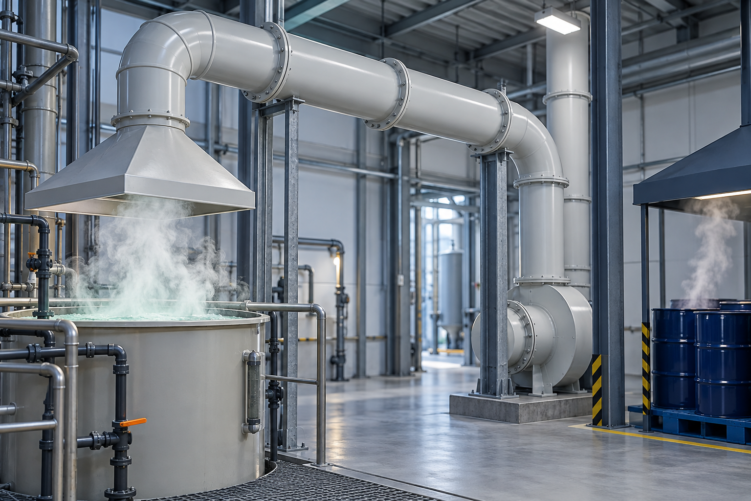
Once local exhaust is set, the material follows the media. Classify each stream — acid fume, alkali mist, solvent vapour or oxidizing gas — before you shortlist a chemical plant ventilation duct material.
| Media class | How it attacks | What it rules out | First-line answer |
|---|---|---|---|
| Acid fume (hydrochloric, sulfuric and similar mists) | Metal corrosion, worst at cut edges and condensation | Galvanized and carbon steel | PP; FRP for aggressive acid duty |
| Alkali mist | Attack on zinc, aluminum, incompatible coatings | Zinc-coated steel, aluminum | PP |
| Solvent vapour | Dissolution and swelling of plastics/coatings | Many plastics and coatings | PP after datasheet confirmation |
| Oxidizing gas (chlorine-bearing, ozone-rich streams) | Oxidative degradation of polymer chains | Common thermoplastics under sustained load | Case-by-case datasheet check |
Polypropylene leads the acid and alkali rows on a pH 1–14 envelope; the other rows exist because damage routes differ.
How Each Gas Class Attacks a Duct
Hazardous-exhaust engineering practice sorts failure into three routes: corrosion destroys metal chemically, dissolution swells or softens plastics and coatings, and melting follows sustained over-temperature, not chemistry. A duct that survives one route can fail another.
The same “corrosion resistant” label can hide different failures: a solvent stream that leaves metal untouched can dissolve a plastic liner, while an acid mist that a thermoplastic shrugs off eats galvanized steel at every cut edge. Classifying the gas first turns corrosive gas ventilation from a slogan into a material decision.
Material Boundary Conditions You Must Verify
Shortlist by row, then verify the envelope. Polypropylene works across −15 °C to 80 °C within the pH 1–14 range; solvent and oxidizer streams are confirmed case-by-case against the datasheet, and service life can reach up to 50 years under specified operating conditions. Every boundary moves with grade, concentration and temperature — the envelope is a quotation confirmation, not a universal pass.
| Material | Chemical envelope | Temperature | Watch-outs | Duty fit |
|---|---|---|---|---|
| PP | pH 1–14, acids and alkalis | −15 °C to 80 °C | Solvent and oxidizer streams: datasheet check | Mainstay acid-fume and alkali-mist duty |
| PVC | Good general acid/alkali resistance | Lower ceiling than PP (check datasheet) | Manufacturers report PP as tougher than PVC | Milder duty |
| FRP | Strong with acids, including hydrofluoric | Set by the resin matrix | Resin choice drives the limits | Aggressive acid service |
| SS316 | Solvents and many oxidizing acids | Seldom the limiting factor | Vulnerable to chlorides and reducing acids | Solvent-heavy or hotter duty |
| Flame-retardant PP | PP chemistry plus flame-retardant additive | Per grade, confirmed at quotation | Specify the grade when ordering | Fire-sensitive rooms |
Acceptance runs on evidence: bring composition, concentration, temperature and moisture — the datasheet confirms the row. Can PP duct handle solvent vapours? The pH 1–14 envelope covers acids and alkalis; solvent streams are a case-by-case datasheet confirmation. The corrosive-fume material selection guide carries the full comparison. Classify the media first, then choose the material row — and verify the envelope against the datasheet before you specify.
Organizing a Negative-Pressure Acid Fume Exhaust System
Keep the chemical plant ventilation duct system under negative pressure with the fan at the end of the run — leaks then draw inward instead of pushing fume into the workroom, and branch and main velocities stay inside a working band. Fix these five elements before any diameter is chosen.
| Element | Where it sits | Design note |
|---|---|---|
| Hood and capture point | Within 1.5 duct diameters of the emission source | Capture geometry first; distance costs velocity fast |
| Branch and main duct | From each hood to the fan inlet | Transport velocity keeps effluent airborne |
| Air cleaner, where duty requires | Between main duct and fan | A scrubber is its own equipment decision — match it to the stream |
| Fan at the end | Immediately upstream of the stack | Placement sets the whole run negative; leaks draw inward |
| Discharge stack | Clear of intakes and occupied levels | Dispersion depends on siting, not only height |
Each row is a siting decision: capture distance fixes airflow, ductwork carries it, and the fan’s static-pressure budget ties the path together.
Negative Pressure Layout: Hood to Fan to Stack
The path runs hood to branches to main to fan to stack — the five elements CCOHS guidance uses for any local exhaust system. With the fan at the end, everything upstream sits below atmospheric pressure, so a loose joint pulls plant air in instead of leaking fume out.
Fan selection follows from that layout: the fan must overcome the static pressure accumulated along the run — hood entry losses, duct friction, cleaner pressure drop where fitted — plus system effect at its connections. Undersizing shows up as weak capture at the farthest hood, not as an alarm.
Make-up Air: The Hidden Half of the Design
Exhausting air without replacing it starves the system: CCOHS guidance notes that a room left short of make-up air goes negative, drags air in through cracks and doors, and the fan moves less air than the schedule promised — capture weakens first at the farthest branches. Plan make-up air from the same airflow schedule, and judge the balance by how a door behaves before trusting the drawing.
What velocity should chemical exhaust ducts run at? Main runs for corrosive effluent typically sit between 500 and 2,500 fpm — the floor keeps condensate and particles moving, the ceiling keeps friction and fan energy sane. A 40% increase in velocity roughly doubles pressure drop and nearly triples fan energy in that section. The ventilation duct sizing and design guide carries the full pressure-loss calculation. Specify the layout direction, the velocity band and the make-up air premise together — the quote is wrong if any one is missing.
Chemical Plant Ventilation Duct at Diameter: Reinforcement and Joints
Above 500 mm, chemical exhaust ducting leaves injection molding behind: the run is bent and welded from polypropylene sheet and reinforced with external flanges against deformation. Below that range, injection-molded sections keep machine-set uniformity — and either way, the joint system is specified per run, not per catalog.
| Run size | Fabrication method | What to check |
|---|---|---|
| Below 600 mm | Injection molded | Uniform wall thickness and consistent dimensions |
| Above 500 mm | PP sheet bent and welded, flange-reinforced | External flanges carry the deformation load |
| Section length | 3 m sections with 2 external flanges | Reinforcement spacing per section |
| Joint sealing | Closed-cell sponge rubber flange gasket ≥5 mm | Gasket material matched to the stream |
The table reads as a threshold, not a preference: injection molding serves diameters up to 600 mm, and sheet welding takes over where deformation begins — flanges carry the load. Whatever the diameter, a flanged joint only seals through its closed-cell sponge rubber gasket, and 5 mm is the working floor.
Why Large Thermoplastic Runs Need Flange Reinforcement
A wide thermoplastic shell deforms past 500 mm, so the fabrication route changes — PP sheet is bent to shape and welded, then stiffened with external flanges. Reinforcement is part of the fabrication method, not an accessory added later.
Metal systems lean on gauge and locked seams; thermoplastic quality lives in construction — a weld defect, an off-square joint or an unsupported span is the failure point aggressive effluent finds first. Workmanship is a material property in corrosive service.
Welded, Flanged or Socket: Keeping One Sealed Circuit
Flanged joints suit high-strength, high-sealing duty and come apart for maintenance; socket joints weld a sleeve at each section end for fast field insertion; hot-air welding produces the continuous sealed line when the circuit must stay monolithic. Per LEISTER’s hand-welding parameters based on DVS 2207-3, welding air sits at 305–315 °C measured about 5 mm from the nozzle centre, travel runs at 60–85 mm/min, and a 3 mm rod takes roughly 8–10 N of pressure — rod matched to the base material, and test coupons welded before production runs. Our installation guide details the welding steps.
Acceptance follows the same logic: weld continuity is the premise of system air-tightness, and a flanged run buys its disassembly with gasket discipline. Choose the fabrication method by diameter, and specify the joint type per run — welded where the circuit must stay monolithic, flanged where maintenance access wins.
Hazardous Exhaust Requirements for Chemical Storage and Process Rooms
Two code triggers decide when a chemical room needs dedicated exhaust: Group H exhaust for storage above allowable quantities, and hazardous exhaust for open operations that release dangerous vapours. Where either applies, a thermoplastic run joins the scope through a flame-retardant grade and datasheet acceptance.
| Trigger or requirement | What it asks | What it means for a thermoplastic run |
|---|---|---|
| Group H storage exhaust | 1 CFM/ft² of room floor area | Serves a continuously operating dedicated system |
| High/low exhaust | Takeoffs within 12 in. of ceiling and floor, by vapour weight | Branch layout reaches both levels before diameters are fixed |
| Continuous operation + exterior shutoff | Runs while chemicals are present; shutoff outside the room | Fan and controls sit on the same drawing as the duct |
| Hazardous exhaust thresholds | Above 25% of LFL; health-hazard 4 at any concentration; 1–3 rated above 1% of LC50 | Trigger review decides if the run enters this scope |
| System independence | Separation from other ventilation by rated construction | Plan a dedicated path; shared runs are rarely available |
These figures are summary practice — per the IMC as summarized by Code Red Consultants, the project’s adopted code edition governs. Use them to anticipate the code; confirm each requirement against the edition your jurisdiction adopts.
Two Code Triggers: Group H Exhaust vs. Hazardous Exhaust
Group H exhaust attaches to indoor chemical storage whose quantities pass the maximum allowable quantities per control area; hazardous exhaust attaches to the operations themselves, once vapour levels would pass the thresholds above without exhaust running. The two can coexist in one building, and some rooms need both.
Does chemical plant exhaust need emergency ventilation? The answer lives in your adopted code: the trigger, the exhaust rate and the controls belong to the edition your AHJ enforces and to the engineer who signs the design. The tables above map what those requirements ask; they do not set numbers for your plant.
Specifying Thermoplastic Duct Inside Hazardous Exhaust Scope
Fire provisions generally expect noncombustible duct, with a narrow exception for non-metallic runs whose flame-spread index is 25 or less and smoke development is 50 or less under ASTM E84/UL 723-type testing, as summarized in laboratory-planning practice. That exception is where flame-retardant PP earns its place — specify the grade at quotation.
XICHENG PP duct is not a UL/FM-listed product — acceptance runs on the product datasheet. Put the media data and the fire requirement on the same specification sheet, so the supplier confirms the chemical envelope and flame-retardant grade in one pass.
Verify the adopted code edition with your AHJ, then decide whether the run stays metallic or specifies flame-retardant PP with datasheet acceptance.
From Worked Example to RFQ: What to Send the Supplier
A quote that comes back right the first time carries ten fields and their boundary conditions — a worked example shows how the chain fills each one, and the same fields serve any corrosive stream.
Worked Example: Acid Fume Line in a Fine-Chemical Plant
Take a fine-chemical plant branch line over an open reaction tank: acid fume, ambient duty inside −15 °C to 80 °C, branch diameters within the standard φ20–600 mm series. For this chemical plant ventilation duct run, the chain fills itself:
1. Fix the duty: acid fume, ambient, pH 1–14 envelope, branch sizes from the φ20–600 mm series. 2. Classify the media: the acid row rules out galvanized and carbon steel. 3. Choose the material row: PP — acids and alkalis on the pH 1–14 envelope, −15 °C to 80 °C. 4. Organize the system: negative pressure with the fan at the end, main velocity between 500 and 2,500 fpm, make-up air on the same schedule. 5. Engineer the run: below 600 mm stays injection molded; flanged joints seal on gaskets of at least 5 mm. 6. Check the code trigger: whether stored quantities pass the Group H or hazardous-exhaust thresholds belongs to the adopted code edition — a project-level verification. 7. Change a condition: add solvent vapour to the stream and the material row moves to case-by-case datasheet confirmation — PP holds only until the media data says otherwise.
A material row is only as good as the media data behind it.
The RFQ Field List
Ten fields cover what a supplier needs to quote a corrosive duct line.
| Field | Why it matters | Example entry |
|---|---|---|
| Gas composition | Sets the media class and the attack route | Acid fume, confirmed at quotation |
| Concentration and moisture | Moves the envelope and condensation risk | Stream data per operating point |
| Temperature envelope | Bounds the material grade | −15 °C to 80 °C, confirm per grade |
| Duct shape and diameter | Drives fabrication route and reinforcement | Round; sizes from the φ20–600 mm standard series |
| Wall thickness and material grade | Matches pressure duty and fire scope | Standard or flame-retardant PPs — grade specified |
| Static pressure and airflow schedule | Sizes the fan and every section | Fan schedule plus capture points |
| Connection method per joint | Sets sealing, maintenance and weld scope | Flange / socket / welded, per run |
| Media confirmation duty | Fixes who verifies the envelope | pH 1–14 confirmed against the datasheet |
| Quantity and section length | Prices sections and reinforcement spacing | Per-run section list with lengths |
| Drawings and destination port | Closes logistics and fabrication detail | Duct schedule, drawings, destination port |
XICHENG’s polypropylene duct page carries the standard size table behind these fields, and the PP exhaust duct page covers round, rectangular and oblate sections. Ten fields and three boundaries turn a chemical plant ventilation duct from a guess into a quote — send them with the drawings, and the material row arrives already decided. For projects where the same plant also runs lithium-battery or energy-storage rooms, the battery and energy-storage exhaust ventilation guide covers the event-exhaust track, the flame-retardant grade question, and the NFPA 855 context that a material page does not.